Getting to Know the Pins on Intel Quark Microcontroller D2000
(The original Chinese version of this article was written by Hsiang-yang Lu and published on MakerPRO)
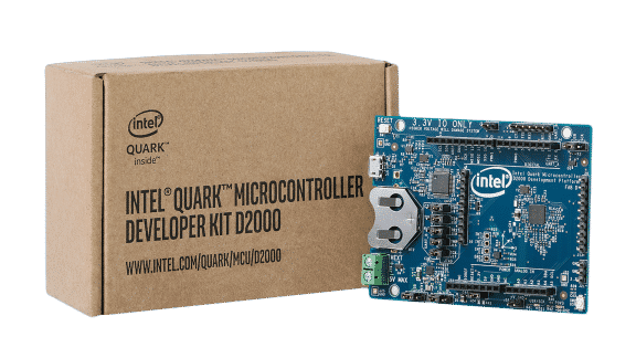
As a newbie Intel Quark D2000 developer, you might feel complicated with the numerous pin headers and jumpers. Since the development board is designed for experts, the board features the delicate settings rather than neat design. That is why there are lots of pins on the board.
A bunch of pins make developers confused so that I did some research with D2000 documentation and found that there’s a little introduction of the pins. But most of the introduction lists the pin functions instead of systematic description.
Therefore, I’d like to help developers to understand the pin functions more and to help those who are working with D2000 still feel confused. Let’s get started!
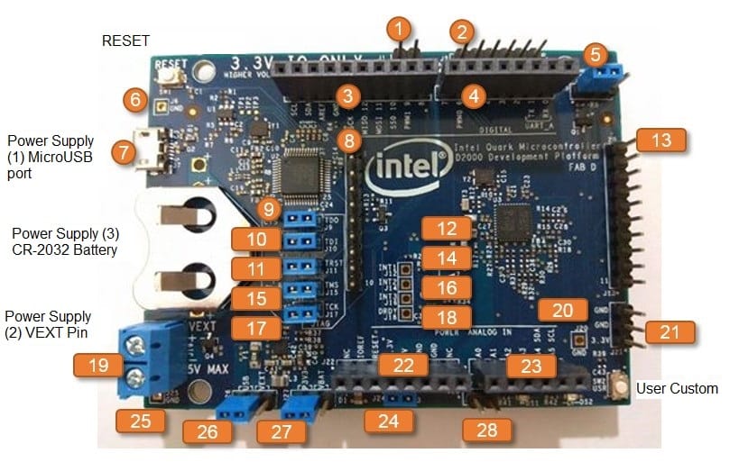
Firstly, D2000 has the pin headers, from J1 to J28, and there are 1 to 10 pins in each pin header. Some of the pins have jumper, which help switch settings. Developers who have used Arduino must be familiar with J3, J4, J22, and J23, which are mechanically compatible with the pins on Arduino Uno R3. However, some pin features are incompatible. For example, the highest voltage D2000 uses is 3.3V, but Arduino Uno R3 can use the higher voltage, 5V.
• J1, 2 pins, is used to select the position of accelerometer/ gyroscope.
• J2, 6 pins, provides 4 functions, USB post, JTAG port, GPIO port, and UART port
• J3, 10 pins, is compatible with Arduino Uno R3.
• J4, 8 pins, is compatible with Arduino Uno R3.
• J5, 3 pins, is used to select digital pin 9 or 13 to connect to LED lights on the board.
• J6, 1 pin, is an empty slot for ground wire. You need to mount a pin to connect the ground wire.
• J7, 5 pins, is a MicroUSB port, not a pin header. At the learning phase, the developers usually get the power supply via the port first and upload the program to the board via the port as well.
• J8, 10 pins, and J13 10 pins. The 2 pin headers are substitution interfaces, which will be discussed later.
• J9, 3 pins; J10, 3 pins; J11, 3 pins; J15 2 pins; J17, 2 pins. The 5 pin headers should be discussed together. The 5 ones are used to switch JTAG and UART so that they are used together generally.
• J12, 1 pin; J14, 1 pin; J16, 1 pin; J18 1 pin.
The 4 pin headers should be discussed together, too. They are empty slot as well as J6. The 4 ones are the external interrupt pins (INT1/INT2/INT3) of Bosch BMC150 chip on development board and 1 Data Ready (DRDY) pin. The reason why the slots are empty is that developers don’t use the external interrupt circuit design by default. If you need to use it, you have to mount the pin. BMC150 provides 3 dimensional magnetic sensors (digital compass) and 3 dimensional acceleration sensors.
• J19, 2 pins, is similar J7, mounted with connector already. It’s an external power supply connector; the highest voltage it uses is 5V. There’s a voltage regulator chip (TPS63051) on D2000, dropping down 5V to 3.3V, to supply the power for the related component on circuit board.
In fact, there are 3 power supplies on D2000, you can choose one of them to use. One is the MicroUSB port 5V of J7, one is 3.3V – 5V of J19, and the other is CR-2032 button cell battery.
• J20, 1 pin, is similar to J6, the empty slot for ground wire.
• J21, 3 pins, provides 3.3V power supply externally or to other components on the boards. You can connect pins to it.
• J22, 8 pins, is compatible with Arduino Uno R3.
• J23, 6 pins, is compatible with Arduino Uno R3.
• J24, 2 pins, is used to decide whether to supply power to Quark D2000 chip. It will be used only when you’d like to use power saving design controlled by external device.
• J26, 3 pins, is used to switch power supply, either from MicroUSB port or J19.
• J27, 3 pins, is also used to switch power supply, either from button cell battery or MicroUSB. J19.
• J28, 2 pins, is similar to J21, the pin for external power supply. The anode is only labeled with +V, so the voltage should be checked or measured.
Lastly, let’s have a look at J8 and J13. The substitution interfaces are the pins mentioned above and one more pin for developer to use. Here is the list of corresponding pins (Jx_y; x is the pin header, y is the number of pin).
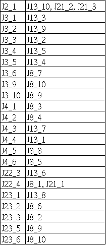
From the table, we can find that most discrete pins are J3, J4, J22, J23, which are compatible with Arduino. When you use the circuit design that is incompatible with Arduino Shield, it will be more convenient to use the substitution interface.
Additionally, we also can see that some pins are similar. For example, J2_1 (the first pin in J2) is for ground wire, and J13 and J12 are for ground wire as well. J22_4 is for 3.3V power supply, and J21 is, too.
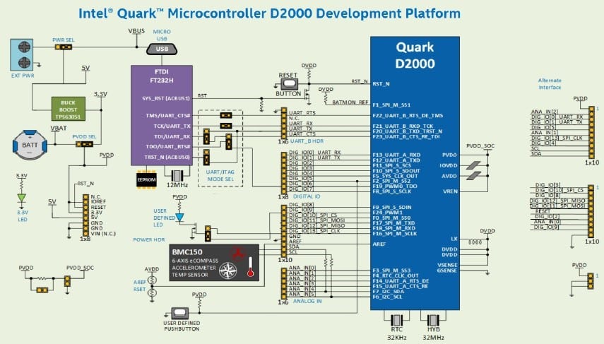
In the last part, I’d like to discuss the main 5 chips on D2000:
• U1: the typical 93LC56B EEPROM memory is used to store the settings of PT232HL chip.
• U2: PT232HL chip from FTDI is responsible to switch UART interface of Quark D2000 to USB interface.
• U3: Quark D2000 from Intel, the master chip.
• U4: BMC150 from Bosch, including 3 dimensional acceleration sensor and 3 dimensional magnetic sensor.
• U5: TP363051 from Texas Instrument, the voltage level regulator chip.
So far, we’ve introduced most of the D2000 hardware information, except SW1 RESET button and SW2 USER button, etc. Hope the article does help those who are interested in D2000 development board.
Read more about Intel Quark D2000:


