Automotive Cluster Meter Development Using Nuvoton’s Microcontrollers – Introduction
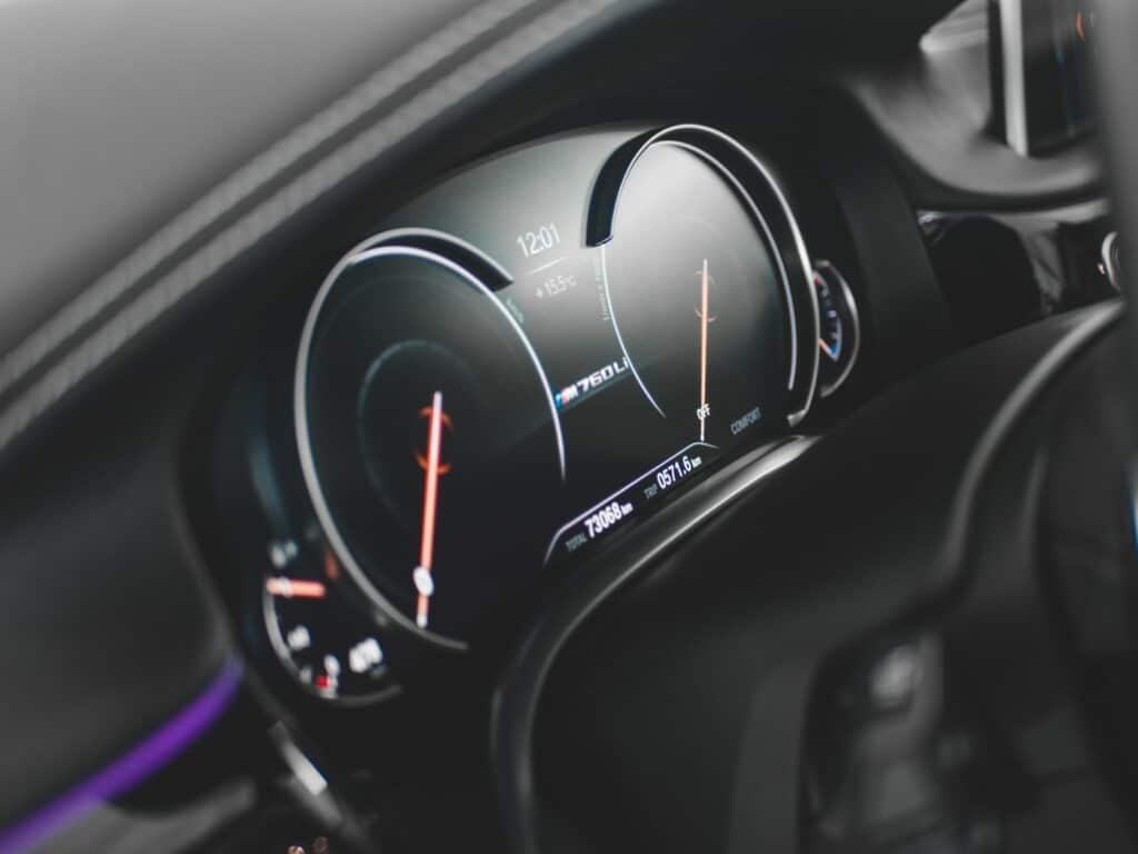
The goal of an instrument cluster is typically to provide the driver with a sophisticated user experience with access to essential information and a safe, convenient, and stress-free drive.
Automotive Industry as a whole is evolving rapidly to meet the changing needs of consumers and the advancement of technology such as connected vehicles, autonomous driving, etc. The usage of electronics has transformed the way vehicles are designed, built, and operated.
This article describes the modern-day digital instrument cluster functions and component selection criteria for designing instrument clusters and how Nuvoton’s microcontrollers can be used in the development of instrument clusters.

Apart from basic functions of a cluster such as speedometer, odometer, tachometer, fuel gauge, basic tell-tale warnings, functions available in modern day cluster meters are as follows:
| Feature | Basic | Premium |
|---|---|---|
| Engine Temperature | X | X |
| Ambient Temperature | X | X |
| Battery Status | X | X |
| Bluetooth/WiFi Interface | X | X |
| Gear Shift Status | X | X |
| Clock | X | X |
| Navigation System | X | X |
| Low Oil Pressure | X | X |
| Engine Checking | X | X |
| ABS Warning | X | X |
| Traction Control Warning | - | X |
| Airbag Warning | X | X |
| Tire Pressure Warning | X | X |
| Lane Departure Warning | - | X |
| Forward Collision Warning | - | X |
| Blind Spot Detection | - | X |
| Rear-End Collision Warning | - | X |
| Adaptive Cruise Control | - | X |
| Parking Assisting | - | X |
Component Selection Criteria for Automotives
For any component used in the automotive application below requirements are critical in achieving a robust design to meet the automotive standard qualification tests.
General Requirements: Below are the few general requirements that should be considered when selecting any electronic component.
| Parameter | Automotive |
|---|---|
| Operating Temperature | -40 ℃ /-55 ℃ to +85 ℃ /+175 ℃ |
| Operation Life Time | at least 10-15 years |
| Tolerable Failure Rates | Zero Failure |
| Humidity | 0% ~ 100% |
| EMI EMC impact | Very High |
| AEC-Q Qualification | Yes |
| Vibration | High |
AEC Qualification: Automotive Electronic Council qualification (AEC-Q) standard is followed globally for electronic parts if they are intended for use within the circuit. The below table shows the classification for the AEC-Q standards. The OEM expectation is to have an AEC-Q qualification for all the components used in the ECU. If the manufacturer uses a non-AEC-Q component then the ECU manufacturer has to do additional stress testing for the product and justify the product meets the requirements. Instead, if the IC itself is AEC-Q rated then ECU manufacturers can produce the certificate and get OEM approval.
| AEC-Q standard | Component Type |
|---|---|
| AEC-Q100 | Integrated Circuits |
| AEC-Q101 | Discrete Semiconductors |
| AEC-Q102 | Opto-Electronics |
| AEC-Q104 | Multichip Modules |
| AEC-Q200 | Passive Components |
AEC-Q Grade Classification:
| Grade | Temperature Range | Application Area |
|---|---|---|
| Grade 0 | -40 ℃ to +150 ℃ | All Automotive |
| Grade 1 | -40 ℃ to +125 ℃ | Most Under Hood |
| Grade 2 | -40 ℃ to +105 ℃ | Passenger Compartment Hotspots |
| Grade 3 | -40 ℃ to +85 ℃ | Passenger Compartment General Area |
EMI EMC Qualification: Electromagnetic interference and compatibility qualification are of prime importance in modern day vehicles as most vehicles consist of various ECUs, and any issues due to this can be fatal failures.
So, designers should ensure they can meet the automotive standard requirements derived by ISO, IEC, SAE, and CISPR standards, and in some cases, OEMs have their own stringent standards derived from general standards.
Electronics components should be able to pass all the below four scenarios:
- Radiated Emission
- Radiated Immunity
- Conducted Emission
- Conducted Immunity
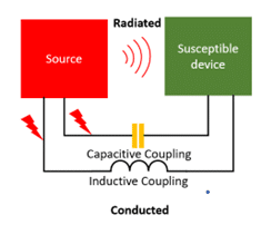
Radiated Emission:
Inside Automotive, there are many sources of emission. An ECU can produce mid-high frequency noises, which can impact the normal operation of other ECUs nearby. For example, audio or infotainment systems can interfere with other ECUs and affect their functions. So as a system, the ECU should be designed to limit the emission. For automotive, CISPR 25 is the standard to be followed, and the ECU should meet the standard’s requirements.
Radiated Immunity:
Radiated immunity is a specific test to be performed on the ECU to observe how the product is functioning when the ECU is exposed to a specified electric field. As explained in the above-radiated emission section, if an ECU emits higher frequencies, our device should be able to withstand the emission and work as per the product’s functional requirements.
Conducted Emission:
Conducted emissions are the disturbances in the quality of power or signal from the ECU, created due to the electrical and magnetic coupling. The system should be designed so that the values do not exceed the limits. CISPR 25 standard defines the frequency ranges and limits.
Conducted Immunity:
Similar to radiated immunity, conducted immunity is a specific test performed on the ECU to monitor the performance when the ECU is exposed to disturbances caused by electrical and magnetic coupling. Standards like ISO 11452-4 and ISO 7637-2 specify the limits and acceptance criteria.
Critical components for automotive cluster meter and design with Nuvoton’s Microcontrollers
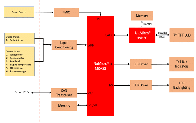
The below block diagram shows the overview of the basic building blocks of the instrument cluster, but depending on the application requirements, features can be added or removed.
Nuvoton’s M0A23 Series for Instrument Cluster development:
NuMicro® M0A23 series is a 32-bit microcontroller based on Arm® Cortex®-M0 core which can be used as shown in the figure 1.
M0A23 series microcontroller has the below features which can be used for data exchange with the circuit and to external interfaces.
| Part Number | Flash (KB) | SRAM (KB) | ISP ROM (KB) | I/O | Timer | PWM | PDMA | Connectivity | DAC | LXT | ACMP | ADC (12-Bit) | Package | |||
|---|---|---|---|---|---|---|---|---|---|---|---|---|---|---|---|---|
| USCI | UART | LIN | CAN | |||||||||||||
| M0A23OC1AC | 32 | 4 | 2 | 18 | 4 | 6 | 5 | 2 | 2 | 2 | 1 | 1 | 1 | 2 | 17-ch | SSOP20 |
| M0A23EC1AC | 32 | 4 | 2 | 26 | 4 | 6 | 5 | 2 | 2 | 2 | 1 | 1 | 1 | 2 | 17-ch | SSOP20 |
| Parameter | Automotive Requirement | M0A23 Series |
|---|---|---|
| Operating Temperature | -40 ℃ /-55 ℃ to +85 ℃ /+175 ℃ | -40 ℃ to 125 ℃ |
| Operation Life Time | at least 10-15 years | Up to 10 years under 85°C |
| AEC-Q Qualification | Yes | Certified |
N9H30 Series for Cluster development
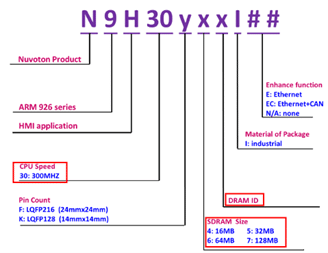
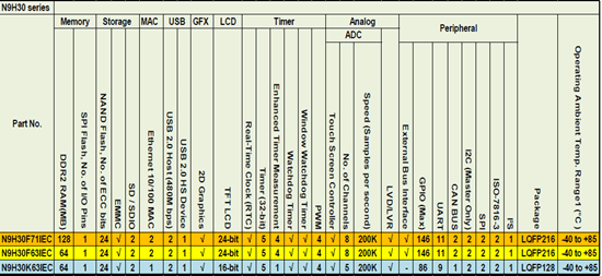
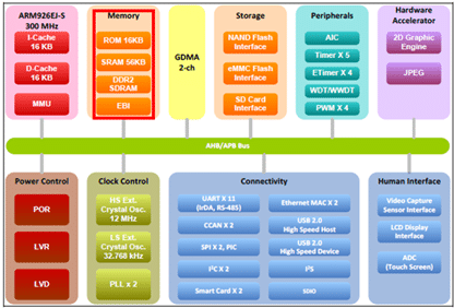
The instrument cluster is one area where an OEM can attract customers with an appealing design and rich graphics. The N9H30 series is a 32-bit microcontroller that embeds an outstanding CPU core ARM926EJ-S,and meet the hardware, software, and architectural requirements of a typical instrument cluster.
Running the data in the instrument cluster is an intensive task requiring larger memory to be allocated to store the graphic data and faster refresh rate. The N9H30 series integrates a DRAM interface that runs up to 150MHz, supporting DDR and DDR2 type SDRAM. This, in turn, reduces the overall BOM cost of needing an additional external SDRAM. N9H30 provides MCP (Multi-chip package) to ensure higher performance and to minimize the system design efforts.
Determining the graphical requirements of instrument cluster is also essential in defining the right architecture and component selection. For example, below are the fundamental criteria to be considered during display interface design.
a. Calculating the required frame buffer size and location.
b. Checking the compatibility of framebuffer memory bandwidth requirements vs. the TFT LCD because refreshing the LCD display can require a large amount of bus bandwidth.
N9H30 supports resolution up to 1024 X 768 and SDRAM with a programmable refresh rate. The refresh and power-on control module generates the refresh request signal and SDRAM power-on sequence. The SDRAM controller also supports software reset, SDRAM self-refresh, and auto power-down function.
Part selection guide:
Below block diagram shows an overview of the N9H30 interfaces:
Power management IC (PMIC):
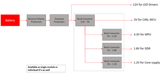
Instrument clusters are directly powered by battery which typically ranges from 12V to 13.5V. PMIC is a switched regulator IC that regulates down/up to voltages for microcontroller, memory, ICs, and functions such as TFT LCD, communication interfaces, and back lighting based on the functional requirements.
Instrument clusters should work in harsh conditions such as load dump, reverse battery polarity, transients, cold crank and warm crank conditions. During these conditions, the cluster is susceptible to large transients on the inputs and outputs of the system which contribute to disturbances in the display, such as distorted segments, missing segments, etc.
So, appropriate input protection is needed for a battery regulator with wide input-voltage range to a constant output in order to protect the downstream components from detrimental input voltage transients.
Signal Conditioning: Various sensor inputs such as fuel level, speed, etc., must be interfaced with the instrument cluster. Signal conditioning circuits provide filtering, amplification, and converting required to make sensor outputs compatible for processing in the microcontroller.
Communication Interfaces: Most advanced clusters nowadays have following communication protocols for data exchange within the cluster and external communication with other ECUs.
- CAN
- LIN
- LVDS
- UART
- SPI
- I2C
- Bluetooth
- WiFi
LED Drivers: The main load types in a cluster is the LEDs used for fault indication and backlighting. LED drivers are typically multi-channel devices with serial interfaces to the uC or Darlington arrays. Constant current LED driver offers the best efficiency as well as excellent brightness control.
Conclusion:
This article serves as a starting point for hardware and software reference for developing an instrument cluster. Still, an In-depth analysis is needed based on the functional requirements. For example, EMC considerations and signal integrity due to transients needs to be analyzed for determining the cluster’s electrical specifications.


