Smart Speaker Development Using Nuvoton’s Microcontroller – M2354 Series
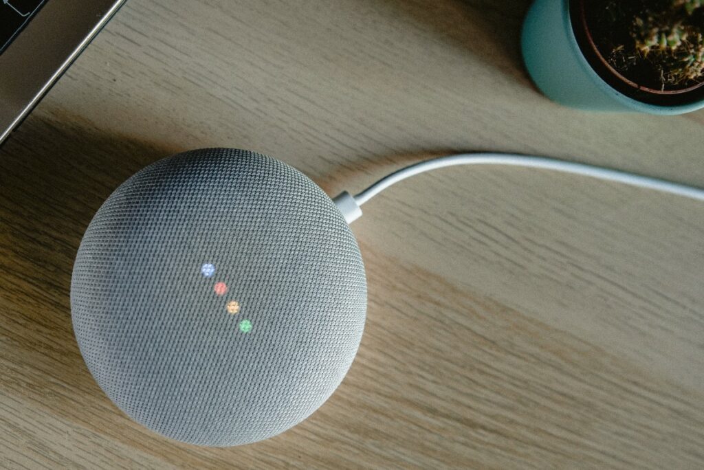
A smart speaker is typically served to provide users with a state of an art audio experience with access to the device connected, a wonderful and convenient user experience.
This article describes how Nuvoton’s M2354 series microcotrollers, based on Arm Cortex M23, can be applied to smart speaker design and why TrustZone features are suitable for smart speaker applications.
M2354 Introduction:
The NuMicro M2354 Series is a Trust Zone for an Armv8-M architecture-empowered microcontroller series focusing on IoT security based on Arm Cortex – M23 CPU technology.
M2354 Features:
- Runs up to 96Mhzs speed i.e., 96Mhz at 1.8~3.63V and 84Mhzs at 1.7V
- 1024 Kbytes of embedded flash memory
- 256 Kbytes of SRAM
- Built-in PMSAv8 Memory Protection Unit (MPU)
- Built-in Security Attribution Unit (SAU)
- Support lower power sleep mode
- Support single cycle I/O access
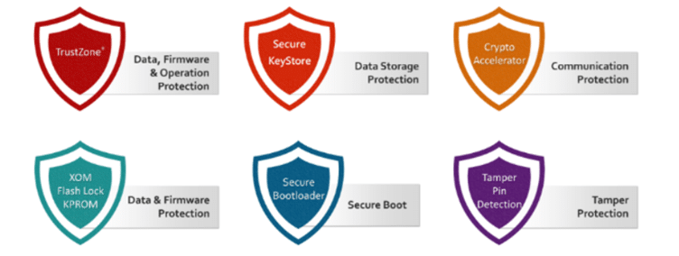
Arm Trust Zone Technology:
Arm trust zone technology is an embedded security technology that starts at the hardware level by creating two environments that can run on a single core i.e., a secure and non-secure world.
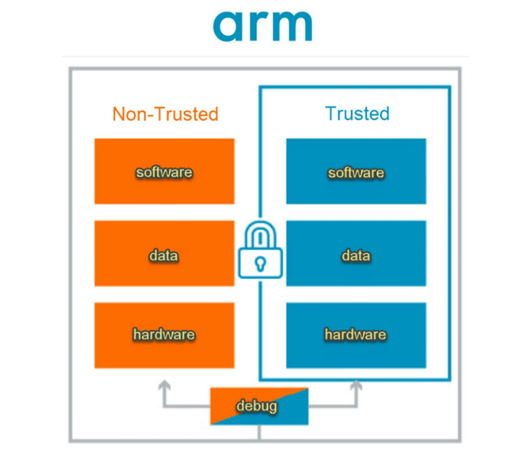
Security is a big challenge for IoT devices. The hacking threats can range from Distributed Denial of Service (DDoS) attacks to unauthorized attacks on internal data. The exposure of the IoT is a concern since DDoS attacks have occurred in millions of unsecured Internet-connected devices. TrustZone includes a secure boot sequence that verifies secure boot images. Images can be cryptographically authenticated using public and private keys.
The key feature of TrustZone in smart speaker is to protect the data received from Bluetooth and Wi-fi interface to leak or tampered and safely save in the trusted zone of the microcontroller.
Nuvoton Secure Microcontroller Platform (NuSMP 2.0):
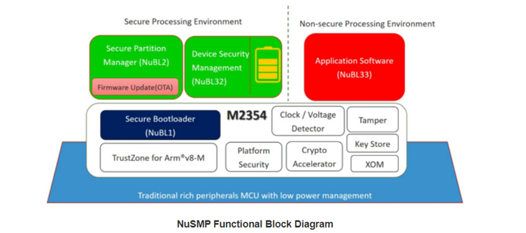
The Platform Security Architecture (PSA) launched by Arm® is an IoT ecosystem security solution. This solution includes threat model analysis, security analysis, hardware and firmware architecture specifications, and open-source firmware reference design. This solution also provides basic design principles, allowing developers to build more secure IoT devices more efficiently. PSA has now developed into three certification levels, namely PSA Certified Level 1, Level 2, and Level 3. Developers can easily implement secure designs on NuMicro® M23 Line microcontrollers through NuSMP technology, including Trusted Boot (Root of Trust), secure Over-The-Air (OTA) firmware updates, software downloads, non-secure zone NuSMP 1.0 can comply with PSA Level 1 and Level 2 security certification, while NuSMP 2.0 imported by M2354 can also comply with PSA Level 3 or other IoT devises.
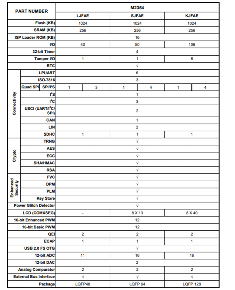
M2354 Series Selection Guide:
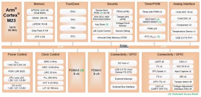
The block diagram below shows an overall overview of the M2354 interfaces:
Power Management Features of M2354:
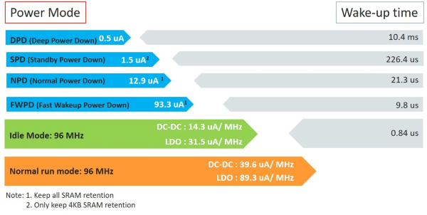
In smart sound box, the power plays a very crucial role. M2354 Series has one of the top-class Internal power managements for IoT Devices with great flexibility. The power management features are highlighted below.
- Normal Run Power mode consumes 89.3uA/MHz with LDO mode and 39.6uA/MHz with DC-DC to Power supply.
- The standby Power-Down mode consumes less than 2uA.
- In Deep Power-down mode with VBAT Power supply, it consumes 0.5uA for 80-bytes Content retention of RTC Register; it can further go down to 0.1uA if there is no need to keep 80-bytes content of RTC Register.
Some of the silent features which make this IC most advantageous over others IC’s are:
- Dual voltage regulator is available for DC-DC converter or LDO
- Supports 1.26V, 1.2V, 1.1V and 0.9V core voltage while operating
- Supports Standby Power-down mode
- Supports Low Leakage Power-down mode
- Supports Ultra-low Leakage Power-down mode
- Supports Fast Wake-up Power-down mode
- Supports Deep Power-down mode
Communication Interfaces:
Most advanced consumer IoT Devices nowadays have the following interfaces for data exchange and peripherals i.e.,
- Trust Zone
- Blue tooth
- Wi-fi
- I2C
- SPI
- I2S
- UART
- RTC
- LCD
- USB
The features above are the major requirements of the smart speaker box; meanwhile, the TrustZone feature of Arm secure the data and that makes M2354 more outstanding than others.
Critical Components for Smart Speaker and Design with Nuvoton’s Microcontrollers:
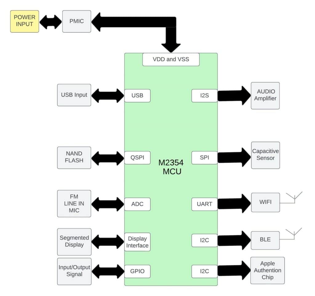
The below Block Diagram in Figure 6 shows the circuits for the smart speaker music box using an M2354 microcontrollers and peripherals connected to it by different ways of communications.
M2354 Circuit Design Guide:
This section talks about the M2354 microcontroller circuits and its interfaces, power supply and protection circuits.
Guidelines for M2354 Circuit design:

The circuits above in Figure 7 shows the power supply connection to the microcontroller, M2354 and by pass capacitor connected to it. Place by pass capacitor near to the power and Gnd pin and lowest value of the capacitor need to be placed first and capacitor ESR value need to be low and try to select appropriate voltage for capacitors for By pass in this application 10V or 16V rated Capacitor should be fine reason for this is chances of capacitor exploding and becoming unstable or defective. LDO capacitor need to be fixed 2.2uF and Inductor 4.7uF.
Oscillator Design:
The high-speed External (HXT) clock can be supplied with 4-24 MHz Crystal Oscillator for precise timing operation. 32.768 KHz low speed external oscillator (exLXT) for RTC Function and low power system operation. For smart speaker application, please place the components as close as possible. Oscillator is stary to capacitance and noise from other signal. It also disturbs signals and EMI noise. Please place C1, C2, C7 and C8 Close to the crystal.
Interface Module:
This section shares the information about the modules needed to interface with smart speaker.
1) Bluetooth Module:
The purpose of this module is to connect with mobile phone or any BT Devices to play music, Attend Calls and read the messages received through Bluetooth. The figure below shows the Bluetooth module connected to the microcontroller.

As shown in the schematics above, Bluetooth module is connected to I2C Bus with pull up resistor of 4K7 resistor.
2) Wifi- Module
The purpose of this is to connect over the air or the Internet to play the music, audio. Figure 9 below shows the circuits.

The above schematics shows the Wifi module connected over UART, the antenna need to be at the edge of the board and avoid the traces pacing below it.
3) LCD Module:
The purpose of this module is to display the contact no, call receiver details and song or lyric name and display song no. The below Figure 10 represent schematics.

The above schematics shows the connection to segmented display; switch is used to shift the segment of display and C_VLCD is placed near the power pin of the LCD module.
4) I2S Speaker:
The purpose of this module is to connect to speaker for music output and connected to the SPI Bus. The below Figure 11 shows the circuits.

The above Figure shows the circuit connected to the speaker and Ferrite bead; capacitors need to be routed directly to the speaker. And SPI Bus need to be routed in same layer and with GND Plane.
5) Apple Authentication Chip:
The purpose of this chip is to connect with the Apple devices and connected over I2C Bus. The Figure 12 below shows the circuits.

The above schematics shows the circuits for apple authentication chip and its run over I2C bus and that need to be routed in differential pair with pull up of 2K2 to each line and reset pin need to be grounded.
6) USB Flash Device:
USB connector used here is to connect pen drives to play music and audio from the smart speaker connected over data line D+ and D-. Figure 13 shows the circuits.

The above Schematics shows the USB Circuit for Flash drive and Connected over Data Lines D+ and D-, This data lines need to be routed differently and maintained Impedance of 90 ohms.
Power Supplies Circuit:
Smart speaker is a standalone device; some operate from the battery. And the batteries are rechargeable Ion Battery of 5V 1A and these batteries can be charged through USB port and in the below sections we will see clearly the charging circuit and power regulators needed to drive the circuits in the smart speaker.
Charging Circuit:
USB type A cable is used to charge the Batteries from VBUS and GND. Figure 14 shows the below.

The schematics above shows the 5V input power is used to charge the battery and power on the device. For proper operation, grounding is very important so that solid ground is needed.
Power Regulator to Drive the Circuit:
The purpose of this module is to power the modules on the board and to run the smart speaker. Figure 15 shows the circuits to drive the board.

The above schematics shows the circuits for powering on the microcontrollers and peripherals. Place the capacitors and diode near the chip and trace need to be thicker to drive 2A of current. TVS Diode is used to protect the regulator from sudden spikes in the voltage. The Ferrite bead is used to give the power to each peripheral and reduce the impedance raised due to long routed traces and improve the performance.
Conclusion:
This article introduced the architecture of hardware development for a smart speaker or any IoT devices using the M2354 chipset from Nuvoton. TrustZone feature in this microcontroller makes M2354 suitable for smart speaker.


